Tuesday, December 28, 2010

13 The Art of Plastering

Plastering is a highly skilled job.  It is also back-breaking and laborious.  Any construction worker can prepare and mix plaster but the application is usually left to a skilled "sifu."  Much of the effort lies in the preparation of the "level markings" to ensure that the final results will produce a flat and even wall.

 
Pic 1: These little blobs of plaster which could easily be overlooked by the untrained eye, are part of the methodical process of the skilled plasterer when preparing a wall for plastering.  These "markers" indicate the plaster thickness required at that spot.  When combined with up to a dozen other markers on any given wall, they provide fairly accurate level guides during the plastering process.

Pic 2: A master plasterer at work.  He is usually assisted by another lay worker who prepares the plaster mix and hands it to him in batches.  To ensure a good and even finish, the entire wall should be plastered at one go.

Pic 3: A wall before and after it has been plastered.

Plastering the ceiling requires a different set of skills and is usually performed by a different set of workers.  It is no less tedious and back breaking since it requires the worker to arch over and work over head while balancing precariously on scaffolding which at times, can be several storeys high.

Pic 4: Two types of pre-made plaster boards as base material - normal (on the left) and moisture proof for external areas (on the right).

Pic 5: Mild steel framework mounted in place prior to fixing the plaster boards.

Pic 6: A completed section of plaster ceiling after it has been touched up to hide the visible joints.

Pic 7: External plaster ceiling works being carried out on the 2nd floor back facade of the house.

Pic 8: Scaffolding setup to facilitate plaster ceiling works on the front roof over hang.

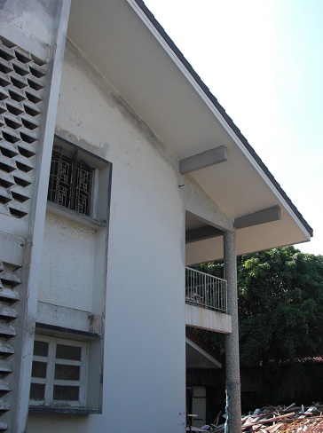
Pic 9: A completed section of the plaster ceiling works on the front roof over hang.

Pic 10: Front facade of the house showing the partially completed plaster ceiling works on the roof over hang.

Sunday, December 26, 2010

12 Recycle, Recycle, Recylce

The saying "old is gold" couldn't be more true especially when considering two important building materials - wood and steel.

By today's standards, tropical hardwood is more expensive than cement and concrete per square foot.  Thus, it made a lot of environmental sense to recycle as much of the "Balau" wood which was used for the roof trusses and prevent it from ending up as landfill.

Pic 1: Removing the original roof tiles exposed the "Balau" wood roof trusses which remained in excellent condition even after 50 years.

Pic 2: The roof trusses were carefully dismantled and sorted according to length.

Pic 3: Any nails or metal objects were removed by hand and then planed using an electric hand planer.

Pic 4: Once planed, the natural grain and colour of the "Balau" wood was clearly visibly.

Pic 5: Each piece was then given a quick protective coating, cut to size and hoisted in place to form the new floor beams.

Pic 6: Close-up view of the floor beams using recycled "Balau" wood.

Pic 7: View of the loft with the floor beams in place and ready for the floor boards to be installed over it.

Pic 8: Bamboo plywood used as underlay for the floor boards.  Bamboo is a renewable product and resistant to termites due to its tough fibers.

Pic 9: The original "Balau" door frames were also re-fitted throughout the house.

Pic 10a & 10b: Vintage steel casement windows and grilles dating back to 1960s were salvaged from an old bungalow and re-fitted in the bedrooms.

Pic 11: Solid steel bars salvaged from the original louvered window grilles will be incorporated into the new grilles.

Thursday, September 30, 2010

11 The Roof - Part 2

The roof, by far, has been the most complex structure to design, build and implement.  Though it looks like any ordinary roof, it isn't.  The specifications were according to industrial standards and suited for a factory rather than a residential building.  Comprising 7 layers and covering an area of approximately 5,300 square feet, the roof took more than a month to construct.  Why all the fuss?  Simple.  It's main purpose was to keep the internal temperature of the house between 26-30 degrees Celsius, 24 hours a day, seven days a week, without the use of active energy!

Pic 1: Week 1 - Calculating pitching and leveling of the concrete roof beams.

Pic 2: Week 2 - Fastening of steel trusses and brackets on the concrete roof beams.

Pic 3: Week 3 - Securing insulation foil and 100mm thick rock wool across the entire roof.

Pic 4: Week 4 - Installation of facia board and final adjustments prior to mounting roof tiles.

Pic 5: Week 5 - Hoisting and laying of roof tiles and dry fixing.

Pic 6: Close-up of C-channel purlins, each measuring 152mm X 66mm X 1.6mm thick, covering an area of approximately 5,300 square feet.

Pic 7: Close-up of 100mm thick rock wool from CSR Australia.

Pic 8: View from underneath showing the steel mesh holding up the insulation foil which in turn, supports the rock wool.


Pic 9: Top view of steel rafters and GCI clay roof tiles prior to laying. Note the reflective foil which adds an additional layer of insulation.

Pic 10: View of the south wing's roof under construction.

Wednesday, August 18, 2010

10 An Unexpected Discovery

While constructing the roof beams, I discovered something rather unexpected.  While standing on the roof, it was possible to see the KL Tower, Petronas Twin Towers and Menara Maybank in the North East direction from the house!  It was also  possible to see some of the other familiar landmarks in Petaling Jaya such as Menara TM, Menara MBPJ, Amcorp Mall and Jaya 33.

Pic 1: Roof top view looking North East. Clearly visible is Menara TM on the right.  Note the KL Tower and Petronas Twin Towers in the distance on the left.

Pic 2: Close-up view of KL Tower and the Petronas Twin Towers as seen from the roof of the house.


Pic 3: Close-up view of KL Tower and the Petronas Twin Towers with Menara Maybank clearly visible on the right.

Due to this discovery, it was decided that the roof should incorporate a roof top balcony that would offer an unobstructed view of the surrounding PJ landmarks as well as the impressive view of the KL Tower and Petronas Twin Towers.

Tuesday, August 10, 2010

09 The Roof

The roof, being the biggest and most important construction element in the overall house design, needed to be carefully planned and constructed.  Simplicity was the guiding principle.  A symmetrical dual pitch roof with a gentle gradient of 20 to 25 degrees on each side was chosen as the basic form.  This eliminated unnecessary ridges and gullies that could become a potential point of leakage.  Spanning the entire width of the house, the roof would stretch over 120 feet from the North wing to the South wing with a single ridge dividing the roof in the middle.


With such a wide area being exposed to the sun and heat throughout the day, it was critical that the roof design effectively overcome the issue of solar gain.  Interestingly, the design drew its inspiration from Land Rover with its safari roof.


The safari roof was a device designed for the Series Type Land Rovers operating in the hot tropics.  A simple sheet of aluminium mounted on top of the vehicle with metal feet, sandwiched a layer of air for insulation, which, when heated sufficiently, dissipated the air along with the heat while drawing in cool air through a repetitive cycle.  More about this later.

In order to support the large expanse of roof, it was decided that large horizontal concrete beams would be constructed at regular intervals. The height of each was staggered to accommodate the pitch of the roof. I called this the "hurdle" design after the track and field sport.  This design was not new but borrowed the design method of the 1960s thereby adhering to the architectural style of the period.


Pic 1: The staggered "hurdle" beams that would eventually support the roof.


Pic 2: South wing extension viewed from the front.


Pic 3: A big challenge was to construct the concrete beam on top of the three main columns two storeys high.


Pic 4: Close-up of the concrete beam as it cures.  Note the circular cap that carries the columns' form all the way to the top.


Pic 5: Top view of the staggered "hurdle" beams and cross support beams.


Pic 6: A panoramic view of the roof beams from the south back corner of the house showing the systematic construction process from south to north.


Pic 7: The same view but from the opposite end of the house.

Sunday, July 25, 2010

08 Bio-Climatic Based Design Principles

The house was designed along bio-climatic principles.  This meant that particular emphasis was paid to the impact of energy, material and water on the building's function and an overall responsiveness to the local climate. Design solutions had to be passive i.e. low energy / non-dependent on fossil fuels / renewable, and as much as possible integrate with the surrounding vegetation.

Working closely with sustainable experts and using advanced computer software, it was possible to virtually model the facade design, orientation and solar impact on the house.


Pic 1: Basic 3D virtual model.
Pic 2: Front facade option incorporating the use of potential green / plant walls and other solar shading devices.


Pic 3: Front and side facade option viewed from a different angle.